
How To Build Your Own Motorized Slider for About $75
About six years ago, when time lapse sequences of the night sky were all the rage, I wanted to experiment with it myself and designed a cheap motorized slider that was ultimately too unreliable and impractical for serious use, and I started thinking up a new design. In the process, I discovered extruded aluminum rails from Openbuilds and a couple others. A strong and lightweight piece measuring one meter long (~40 inch) would cost only $20, and I decided that it would be a great foundation for a new design.
The $75 estimate for this project is a bit optimistic, as it doesn’t include shipping costs and assumes that you’ll have the necessary tools already. It’s certainly possible if you can source things locally, though, or get things with free shipping or through AmazonPrime.
Here’s what it looks like in action:
The Simple Version
As I was figuring things out, I decided to make a simple, analog-controlled version that would be inexpensive (and use parts that I already had handy), and I’d use it as an intermediate step while working on a digitally-controlled, Arduino-based version. This is the simple version.
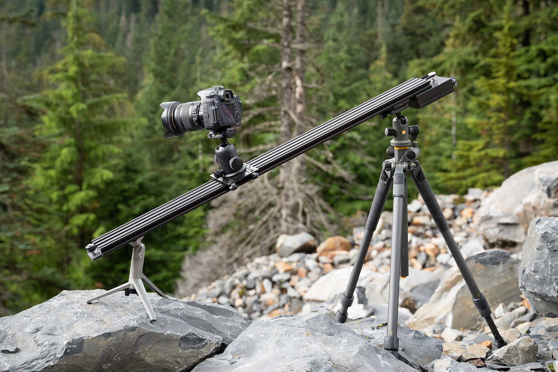
Physically, it’s sturdy and professional looking. Mine is all black, but you could save a couple of dollars if you wanted to buy plain metal hardware. One of the benefits of this design is that even though it looks nice, it’s simple to build and is adjustable enough that it doesn’t require a ton of precision when building (though of course, some precision helps).
Construction
Rail
This extruded aluminum rail is a meter long and, at about $20, is the most expensive piece of the project. These rails are available in a variety of lengths, and can also be joined together with others if you start with a shorter one to start out with and need something longer for another project.
Gantry Plate
The plate that carries the camera and ball-head is called the “gantry plate”, and it can be made of just about anything. To save time, I bought one from Openbuilds when I bought the aluminum rail, but there’s no reason that you couldn’t just buy an aluminum plate (or steel, or wood, etc) and drill five holes into it. To fit this rail, the holes need to be about 112mm apart (on centers).
Pulley Plate & Mount
At one end of the rail you’ll need to mount a pulley to route the belt back through the center channels of the rail. These are also pretty inexpensive to buy, but for my purposes, I decided that it made more sense to buy a 12″ chunk of 1/4″ thick, 2″ wide aluminum bar ($7), which I cut into a few pieces.
The largest piece is about 5.5″ long, though it could be a little longer or shorter. At one end, I drilled a centered hole for a bolt to hold the pulley in place, and I drilled an additional six holes in line with the rail slots to mount it to the rail. Then I drilled and tapped a hole with threads to fit a tripod-mounting screw.
With the second piece (about 3″ long), I also drilled and tapped a center hole for a tripod screw, and drilled four holes for mounting screws, too.
Motor Box
To mount the motor at the other end of the rail, I used an aluminum electronics project box. These are inexpensive online, and I bought a split model that’s easier to work with. I mounted the top half of it to the bottom of the rail by drilling four holes and using the mounting T-nuts in the rail slots. I drilled a hole for the motor shaft and two more little ones for the mounting holes.
A hole drilled in the project box end cap allows the potentiometer to be mounted (just remove and replace the nut from the threaded collar of the shaft). I used a hack saw to make a couple of cuts in the box’s end cap and then bent it down (and off) to create a slot for the switch to be mounted. Not pretty, but it works. A Dremel-cut hole would be even better.
The wiring will look like this, for the Pololu:
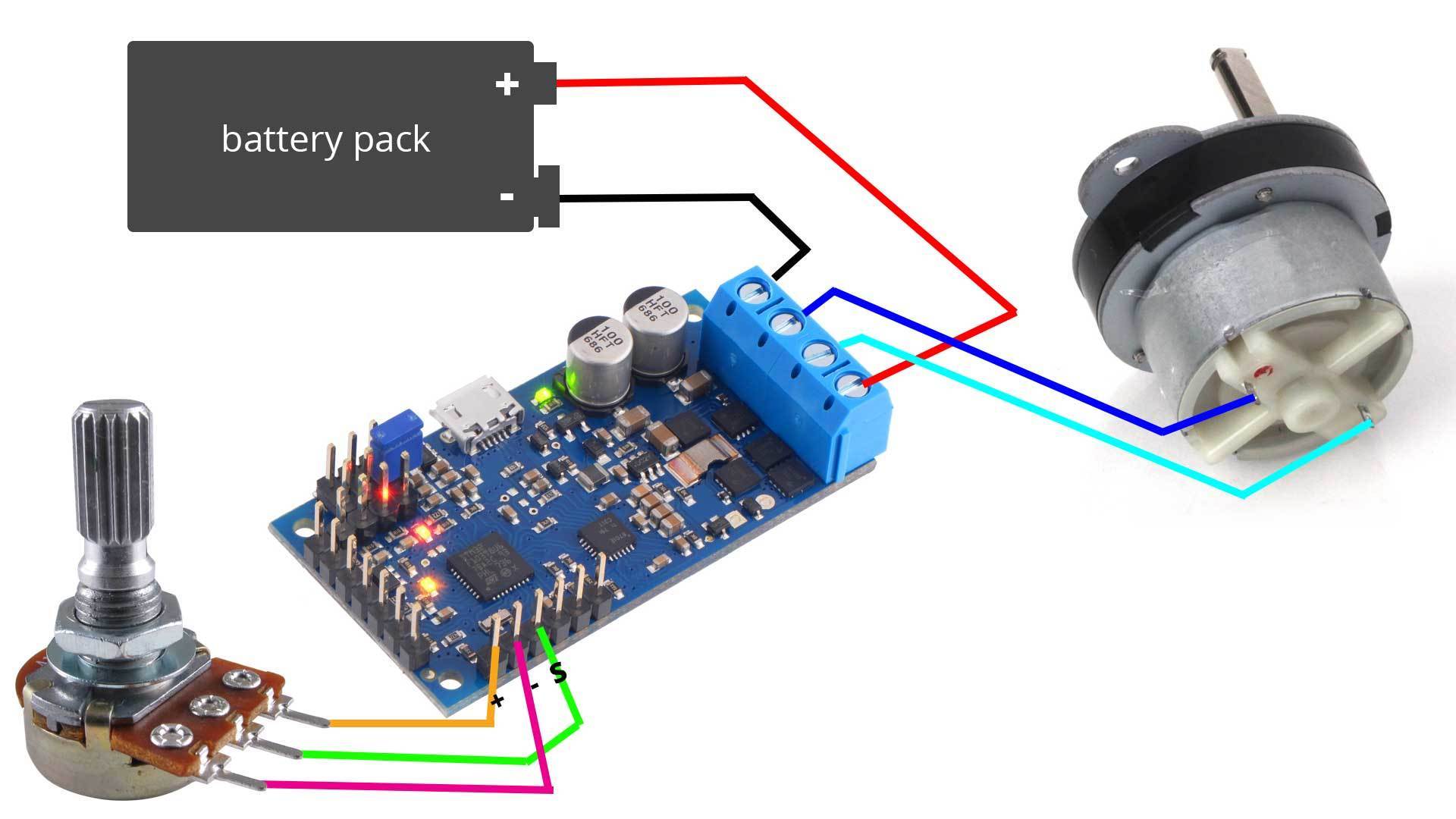
If you buy one of the cheap Amazon controllers, wiring is even easier, since the potentiometer and switch are already wired in. Again, they will provide an easy to follow wiring diagram, usually.
Electronics
If you are familiar with my previous build, I’ve simply re-used the parts from there: same battery pack type (but I used 8 AA batteries this time), same motor, same motor controller, and same potentiometer to adjust them. I added in a rocker switch to turn power it off.
There are also cheaper options available, now. These begin at about $8 on Amazon and include a potentiometer to control the speed, although they add a switch to change direction of the motor.
The more sophisticated version will require all new electronics and a new motor.
Parts List and Sources
My guiding principle while choosing parts was to buy items that were (1) the lowest cost possible while (2) reducing the amount of work necessary while building and while (3) keeping weight low and (4) maintaining the level of quality that wasn’t going to compromise my work or the safety of my camera gear. Consequently, I didn’t always go with the cheapest option, and if you’re comfortable with and have access to tools, there are plenty of places where you can save some money. Below, I’ve included some warnings about choosing different parts that are cheaper or otherwise different, where it matters.
Tools
No special tools are required for the frame, but you will need a drill and a good set of bits. Otherwise, you can get by with a crescent wrench, a set of hex keys (Allan wrenches), a hack saw, and a screwdriver. Also, you’ll need a tap bit to make the threaded holes for the tripod mounts in the aluminum plates.
For the electronics, there are a couple of easy soldered connections to make, so you’ll want a soldering iron. Wire clippers and a couple of small screwdrivers might come in handy, too.
Frame Materials & Hardware
First, let me mention that shipping to the west coast from Openbuilds is expensive: about $20. Make sure that you don’t forget anything that you need, since making two orders will dramatically increase the overall costs. Some of the parts, like the idler pulley and 30 tooth gear, I purchased from Openbuilds because they were the perfect size and couldn’t find them elsewhere, but if you can find a better source, let me know. They occasionally have free-shipping sales, so it might be worth waiting if your budget is very tight.
- 80×20 V-Slot Linear Rail (1 or 1.5 meters long) : I used the wider, 80×20 rail because I liked how it fit with my enclosure box, but a 40×20 would work just as well. These come in lengths of 10, 50, 100, or 150cm, and this build would work just as well with any of them. From Openbuilds or via EBAY or Amazon.
- Aluminum bar ($11) for idler pulley plate/tripod-mounts: This was the simplest way to solve two problems at once. I used a 1/4″ x 2″ x 12″ thick aluminum bar (cut into two pieces) to hold the pulley at the far end, and I also tapped it to accept tripod-mount screws.
- V-Wheels ($7, pack of 5)
- V-Slot Gantry Plate : This is just a plain aluminum plate with holes drilled in it. If you don’t want to spend $12 on it, you can save money by making one out of a scrap of hardwood, MDF, plywood, rigid plastic, steel, or any other material that you have handy (now available on Amazon, complete with wheels for $ ).
- 30 tooth GT2 Pulley ($6.50 Amazon, $7 Openbuilds)
- Idler Pulley ($6 kit from Openbuilds, cheaper but in larger packs on Amazon)
- 2x – Eccentric Spacers (6mm $2 each)
- 2x – Plain Spacers (6mm, $3 for 10)
- M5 Screws, assorted [10 M5 x 12mm (hold plates to rail)
4 M5 x 8mm (hold motor box to rail)
1 M5 x 35mm (holds belt pulley to plate. 35mm is just barely long enough. Consider 40mm.)
4 M5 x 30mm (hold wheels to gantry plate)] - M5 locking nuts (about 10)
- Aluminum Project Box (120x97x40mm, about $12, but look around for good deals)
- Black Spray Paint (optional)
- GT2 Timing belt ($8 for 5 meters)
Electronics Materials
Everything here was simply re-used from my previous build, but since then, I’ve found additional options, which I’ll include below.
- 3RPM (or faster or slower, to taste) Geared DC Motor ($7 from China, $10 if they’re sold out, $ from Amazon)
- Motor Controller ($40 for the Pololu used here (v1 discontinued), $8 for a similar one from Amazon, adds a reverse switch).
- Potentiometer (if using Pololu)
- Power Switch (if using Pololu, rocker switch, toggle switch, slider… etc. Any type you want that is open-close).
- 8 AA Battery Case – ($2+ at Amazon)
- 9v pigtail for battery case, if desired
- solder
- ~20 gauge wire, braided
Questions? Comments?
If you’re building one of these, or just have some questions about it, feel free to let me know in the comment section below.